Difference between solid state relay (SSR) and mechanical relays
There are different types of relays. This article will delve into Solid State Relays (SSRs), exploring their operation and distinguishing them from Mechanical relays
What is Solid State Relay (SSR)?
A Solid State Relay (SSR) is a relay that does not have a moving contact. In terms of operation, SSRs are not very different from mechanical relays that have moving contacts. SSRs, however, employ semiconductor switching elements, such as thyristors, triacs, diodes, and transistors.
Structure and Operating Principle of Solid State Relays (SSRs)
SSRs use electronic circuits to transfer a signal.
1. The input device (switch) is turned ON.
2. Current flows to the input circuits, the photocoupler operates, and an electric signal is transferred to the trigger circuit in the output circuits.
3. The switching element in the output circuit turns ON.
4. When the switching element turns ON, load current flows and the lamp turns ON
5. The input device (switch) is turned OFF.
6. When the photocoupler turns OFF, the trigger circuit in the output circuits turns OFF, which turns OFF the switching element.
7. When the switching element turns OFF, the lamp turns OFF.
Features of Solid State Relay (SSR)
- SSRs are relays that use semiconductor switching elements. They use optical semiconductors called photocouplers to isolate input and output signals.
- The photocouplers change electric signals into optical signals and relay the signals through space, thus fully isolating the input and output sections while relaying the signals at high speed.
- SSRs consist of electronic components with no mechanical contacts. Therefore, SSRs have a variety of features that mechanical relays do not incorporate.
- The greatest feature of SSRs is that SSRs do not use switching contacts that will physically wear out
Have a question?
Types of Solid State Relays (SSRs)
| Type | Load current | Points | Typical relays | |
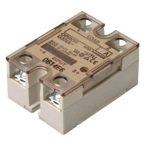
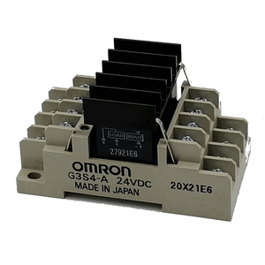
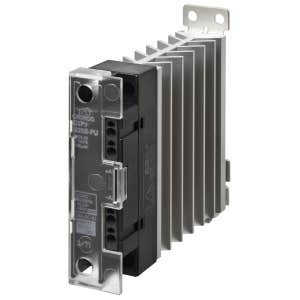
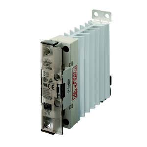
| SSRs integrated with heat sinks | 150 A or lower | The integrated heat sink enables a slim design. These relays are mainly installed in control panels. | G3PJ, G3PA, G3PE, G3PH etc. |  |
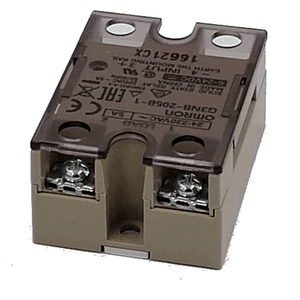
| SSRs with separate heat sinks | 90 A or lower | Separate installation of heat sinks allows the customers to select heat sinks to match the housings of the devices they use. These relays are mainly built into the devices. | G3NA, G3NE, etc | |
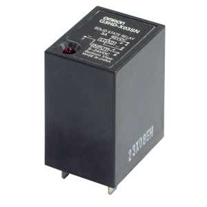
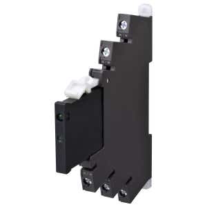
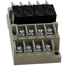
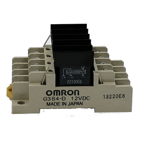
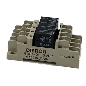
| Relays with the same shapes | 5 A (10 A) or lower | These relays have the same shape as plug-in relays and the same sockets can be used. They are usually built into control panels and used for I/O applications for programmable controllers and other devices. | G3F(D), G3H(D), G3R-I/O, G3RZ, G3TA etc. |  |
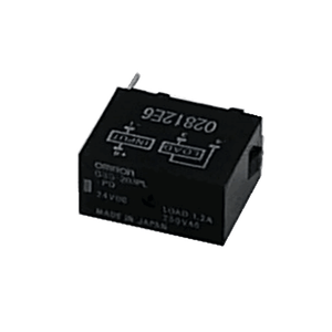
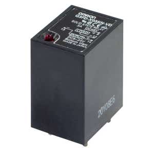
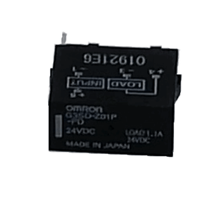
| PCB-mounted SSRs | 5 A or lower | SSRs with terminal structure for mounting to PCBs. The product lineup also includes MOS FET relays, which are mainly used for signal switching and connections. | G3M, G3S, G3DZ, etc. |  |
Control Methods of Solid State Relays (SSRs)
ON/OFF Control
- ON/OFF control is a form of control in which a heater is turned ON and OFF by turning an SSR ON and OFF in response to voltage output signals from a temperature controller. The same kind of control is also possible with an electromagnetic relay, but an SSR must be used to control the heater if it is turned ON and OFF at intervals of a few seconds over a period of several years.
- Low-cost, noiseless operation without maintenance is possible.
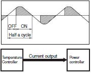
Phase Control (Single Phase)
- With phase control, the output is changed every half-cycle in response to the current output signals in the range 4 to 20 mA from a temperature controller. Using this form of control, high-precision temperature control is possible, and is used widely with semiconductor equipment.
- Precise temperature control is possible.
- The heater’s service life is increased.
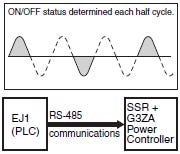
Optimum Cycle Control
- The basic principle used for optimum cycle control is zero cross-control, which determines the ON/OFF status of each half cycle. A waveform that accurately matches the average output time is output.
- The accuracy of the zero cross function is the same as for conventional zero-cross control. With conventional zero cross control, however, the output remains ON continuously for a specific period of time, whereas with optimum cycle control, the ON/OFF status is determined each cycle to improve output accuracy.
- Many heaters can be controlled using communications.
- Noise-less operation with high-speed response is possible
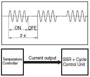
Cycle Control
- With cycle control (with the G32A-EA), the output voltage is turned ON/OFF at a fixed interval of 0.2s. Control is performed in response to current output from a temperature controller in the range of 4 to 20 mA.
- Noiseless operation with high-speed response is possible.
Precautions for Cycle Control
-
With cycle control, an inrush current flows five times every second (because the control cycle is 0.2 s).
-
With a transformer load, the following problems may occur due to the large inrush current (approximately 10 times the rated current), and controlling the power at the transformer's primary side may not be possible.
(1)The SSR may be destroyed if there is not sufficient leeway in the SSR rating.
(2)The breaker on the load circuit may be tripped.
Difference between Solid State Relays (SSRs) and Mechanical Relays
| Mechanical Relays | Solid State Relay (SSR) | |
| Features | Compact More compact than an SSR when the same load capacity is controlled. Enable downsizing of multi-pole relays. Etc. |
Enable high-speed and high-frequency switching. An unlimited number of switching operations. Consists of semiconductors, so there is no contact erosion caused by switching. Zero cross function. No operation noise. Etc. |
| Precautions | A limited number of switching operations. This is because mechanical switching results in contact erosion. Etc. |
Heat dissipation measures are necessary. |
| Selection points |
Electrical Durability Curves
Inductive Load
|
Derating Curves
Example: G3NA (Reference Information)
|
Shop for Solid State Relays

")
Related Articles
Reference:
OMRON: https://www.ia.omron.com/support/guide/18/introduction.html

Share this article on social media