Type 1 & Type 2 Coordination
About Type 1 and Type 2 Coordination
Type 1 and Type 2 coordination was IEC developed criteria of short-circuit performance for starters and contractors. It defines levels of the motor controller’s protection that follow a short-circuit fault. To attain this performance, a mixture of starter or contactor (motor controller), and protection devices (fuse or circuit breakers) should meet the criteria stated by IEC 60947 4-1–control gears and small voltage switchgear, 4-1: motor starters and contractors.
What is Type 1 Coordination?
It demands that during short-circuit situations, the starters or contractors should not cause any damage to installation or persons, and it should no longer be appropriate for service anymore without replacement and repair of parts. In case, substantial damage is permitted to the starter or motor, e.g. burning, disintegration, or contact welding), and to the overload relay, e.g. heater burn-out, or component harm.
What is Type 2 Coordination?
It demands that during short-circuit situations, the starters or contactors should not cause any damage to installation or persons and should be appropriate for future use. Contact welding’s hazards are known, in which the manufacturer should specify the necessary procedures for the equipment’s maintenance. In this, the starter or contractor is right to practice after the short-circuit fault has taken place. Tack welding or contact burning can occur, with the need that the contacts should be simply separable.
Benefits of Type 1 and Type 2 Coordination
- Attaining an acceptable stage of short-circuit coordination needs an understanding of the application, installation codes, product standards, and qualities of various protective devices that exist. Extensive testing should be done and certified to attain a Type 1 or Type 2 rating. IEC proposes brief definitions of permissible damage to direct the users to the correct product and with the correct protection.
- Generally, many users think of Type 2 protection in applications. Sometimes, users may think that Type 2 protection is achieved if the branch components are USA-certified or CE-marked. That is not true. The benefits of Type 2 come with the guarantee that it poses no danger or threat to the installation or person. With the improved emphasis on reducing downtime for the increase in productivity, proper selection and application of circuit devices have become the most important. By choosing the proper kind of protection, the employees and the working environment can be guarded against faulty conditions. In this way, the performance of overload relays and contactors can be enhanced. It provides confidence about the operation of control components after a fault. It translates into savings of dollars due to replacement costs and reduced downtime.
Type 2 coordination= less downtime + safety= cents and dollars.
TYPE W.R.T APPLICATION
- In many circumstances, the chance of a high current short circuit fault is less. It will fit Type 1 coordination.
- In critical conditions, where the chance of a high current short circuit fault is higher, or up-time is crucial, Type 2 coordination should be recommended.
Have a question?
Coordination Types
Many solutions are delivered to attain selectivity based on:
- Current
- Time
- Energy
- Logic
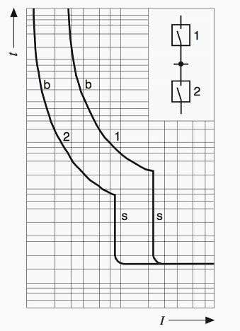
Current Selectivity:
The ratings of the circuit breakers get smaller as we go from the transformer towards the load side. Likewise, the short circuit current’s magnitude also gets lower progressively. The potential short circuit current at the place of fixing of a circuit breaker must be known.
The selectivity of two circuit breakers is analyzed by matching the time and current characteristics. The tripping characteristic may not intersect or touch each other beyond the maximum fault level.
There should be certain spacing between the two circuit breakers characteristics, depending upon the tolerance band.
This comparison method is exact but time-consuming as well.
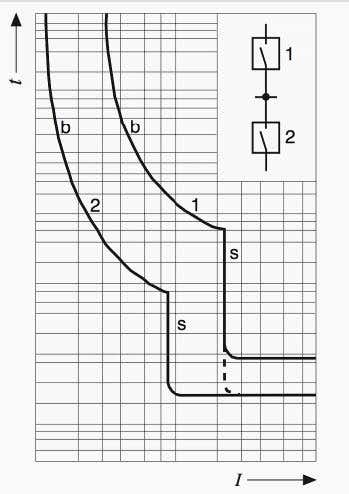
Time Selectivity:
If the current selectivity may not be attained, e.g. both circuit breakers have the same time of reaction then the selectivity has to be judged via the delay time (adjustable).
The minimum time delay realized between the circuit breakers is 60ms or 100ms.
The time selectivity is attained by ceasing the reaction between the contacts and the short circuit current. A delaying mechanism delays the circuit breaker action.
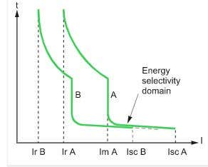
Energy Selectivity:
The contacts between the 2 circuit breakers (A and B) open when a large SC current is sensed by them. So, the value of the current is limited.
- The high energy at B causes the circuit breaker B to tripping.
- Therefore, energy is inadequate at A and cannot cause the tripping of circuit breaker A
This approach needs correct coordination between tripping energy and limitation levels.
Logic Selectivity:
This selectivity is attained with CBs that are equipped with trip units (Masterpact/ compact). Short-term protection is achieved by this selectivity method. Specifically, the function of instantaneous protection is not really a concern.
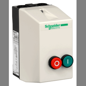
Shop for Motor Starters
-
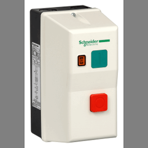
 TeSys LE - Enclosed DOL Starter - 9 A - 415 V AC Coil.
Schneider
SKU: SE_LE1D09N7
Model: LE1D09N7
SGD $123.13 -
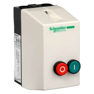
 TeSys LE - Enclosed DOL Starter - 18 A - 415 V AC Coil.
Schneider
SKU: SE_LE1D18N7
Model: LE1D18N7
SGD $242.13 -
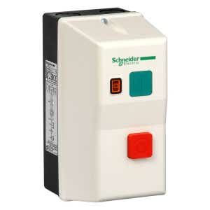
 TeSys LE - Enclosed DOL Starter - 8...11.5 A - 415 V AC Coil.
Schneider
SKU: SE_LE1M35N716
Model: LE1M35N716
SGD $122.71 - TeSys LE - Enclosed DOL Starter - 3.7...5.5 A - 415 V AC Coil.
Schneider
SKU: SE_LE1M35N712
Model: LE1M35N712
SGD $113.85 - TeSys LE - Enclosed DOL Starter - 12...16 A - 415 V AC Coil.
Schneider
SKU: SE_LE1M35N722
Model: LE1M35N722
SGD $132.33 - TeSys LE - Enclosed DOL Starter - 2.6...3.7 A - 415 V AC Coil.
Schneider
SKU: SE_LE1M35N710
Model: LE1M35N710
SGD $113.85 - TeSys LE - Enclosed DOL Starter - 5.5...8 A - 220 V AC Coil.
Schneider
SKU: SE_LE1M35M714
Model: LE1M35M714
SGD $122.71 - TeSys LE - Enclosed DOL Starter - 12 A - 415 V AC Coil.
Schneider
SKU: SE_LE1D12N7
Model: LE1D12N7
SGD $143.66 -
 Enclosed DOL starter,TeSys LE,1.8-2.6A,400V AC coil,including 1 LC1K,LR2K,2 pushbuttons,yellow indicator
Schneider
SKU: SE_LE1M35V708
Model: LE1M35V708
SGD $98.88 - TeSys LE - enclosed DOL starter - 0.8...1.2 A - 400 V AC coil
Schneider
SKU: SE_LE1M35V706
Model: LE1M35V706
SGD $119.15 -
 TeSys LE - enclosed DOL starter - 35 A - 440 V AC coil
Schneider
SKU: SE_LE1D35R7
Model: LE1D35R7
SGD $441.55 -
-
 TeSys LE - enclosed DOL starter - 2.6...3.7 A - 230 V AC coil
Schneider
SKU: SE_LE1M35P710
Model: LE1M35P710
SGD $95.45 -
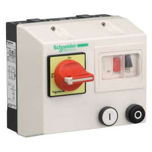 TeSys LG - enclosed DOL starter - 4...6.3 A - 380/400 V AC coil
Schneider
SKU: SE_LG1K065Q710
Model: LG1K065Q710
SGD $574.77 - TeSys LG - enclosed DOL starter - 1.6...2.5 A - 380/400 V AC coil
Schneider
SKU: SE_LG1K065Q707
Model: LG1K065Q707
SGD $574.77 - TeSys LG - enclosed DOL starter - 1...1.6 A - 380/400 V AC coil
Schneider
SKU: SE_LG1K065Q706
Model: LG1K065Q706
SGD $574.77 - TeSys LG - enclosed DOL starter - 4...6.3 A - 220/230 V AC coil
Schneider
SKU: SE_LG1K065M710
Model: LG1K065M710
SGD $582.67 -
 TeSys LE - enclosed DOL starter - 5.5...8 A - 230 V AC coil
Schneider
SKU: SE_LE1M35P714
Model: LE1M35P714
SGD $124.29 -
 TeSys LE - enclosed DOL starter - 35 A - 110 V AC coil
Schneider
SKU: SE_LE1D35F7
Model: LE1D35F7
SGD $363.95 - TeSys LE - enclosed DOL starter - 25 A - 230 V AC coil
Schneider
SKU: SE_LE1D25P7
Model: LE1D25P7
SGD $273.66

Share this article on social media